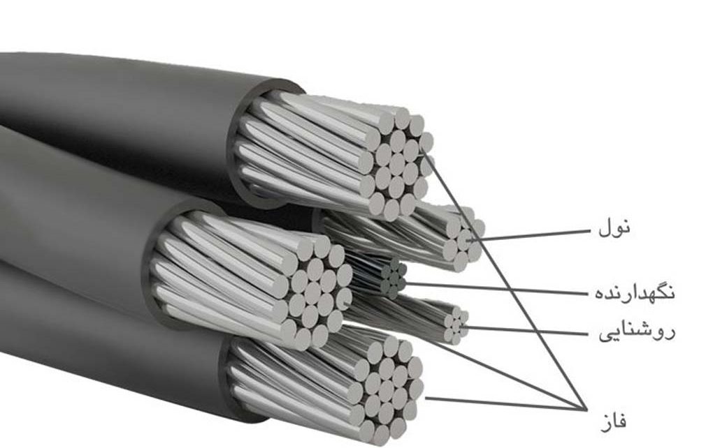
In this article, we have examined the structure of self-supporting cable.
Material and class of self-supporting cable conductor :
Conductor material ( Phase, zero and brightness) Made of aluminum with minimal purity 99.5% Regularly spun with a compressed round cross section (Class 2) And preservative material (Messenger), Is galvanized steel.
Specific electrical resistance of phase, neutral and lighting conductors in thermo 20 °C max 0.868 Ohm per kilometer and the tensile strength of the strings stretched between 12.5 Ta 205N/mm2 should be.
Self-supporting cable insulation material :
XLPE blend (Cross-linked polyethylene)
Technical Specifications:
- Maximum conductor temperature in normal working mode: 90 C
- Maximum conductor temperature in short circuit mode (For a maximum of five seconds): 250 C
- Rated voltage: 0.6up to 1 kV
How to specify cable strands:
- Phase 1: A longitudinal raised line on the surface of the wire
- beat2: Two longitudinal raised lines on the surface of the wire
- Phase 3: Three longitudinal raised lines on the surface of the wire
- Noel: Uniform distribution of the longitudinal embossing line on the surface of the wire
- Illustrated: No longitudinal embossing line (flat)
- Messenger: No longitudinal embossing and cable specification printing on it
Reference standard:
Based on the requirements of Tavanir
The main advantages of using self-supporting cable in overhead power distribution networks:
- Increasing the reliability of the network against weather conditions and events caused by the collision of foreign objects
- Significant reduction of undistributed energy
- Reducing the cost of pruning in forested areas
- Reduce losses by eliminating leakage currents in trees and equipment
- Reduce the risk of fire in wooded areas and prevent environmental degradation and animal death
- More freedom of action in the design of lines due to the reduction of the distance of the self-supporting cables
- Ability to install a new line of self-supporting cable next to the previous line on a pole
- Possibility of installing low pressure self-supporting cable on the existing bases of the lines 20 KV
- Ability to install telephone lines and fiber optics on a common base while maintaining the privacy of half a meter
- Easier repair of broken beams in self-supporting cable lines compared to conventional airlines and continued service to subscribers
- Possibility of beautifying the city by hiding self-supporting cables from public view by passing the cable through the wall or hiding it in special channels
- Resistant to corrosion and thus reduce rupture of weak pressure lines
- Reduce the amount of unauthorized use of electricity
- Low and compensable cost difference from blackout damage savings location
- The possibility of maintenance and service when the line is energized
- Reduce maintenance costs (Systematic reduction of tree branching and replacement of broken insulators…)
- Increasing safety while working on lines and reducing damages and incidents caused by electric shock
- Can be used in narrow passages
- Reducing the possibility of overvoltages caused by lightning
- Unlike bare wires, self-supporting cables (self damping) Therefore, their vibrations due to the wind are insignificant and the possibility of lengthening the spans is possible.
- Use of low-class bases due to the lightness of the cable
- Because the weight of the cables is light and they are bundled, the installation time is shorter.
- The possibility of using short bases due to the insulation of the conductors
- The possibility of increasing the capacity of the line and installing a new circuit on the bases
- Low reactance of self-supporting cables compared to aerial wire network